MURANG HALAGA MAY SOLAR SETUP KANA Circuit Diagram The battery is used to power our device (Arduino, ESP8266 etc) when the energy supply from the photovoltaic panel is insufficient (for example on particularly cloudy days and at night). A DC/DC converter (optional): if the voltage supplied by the battery is lower than the operating voltage of the device to be powered, it is best to use a DC/DC

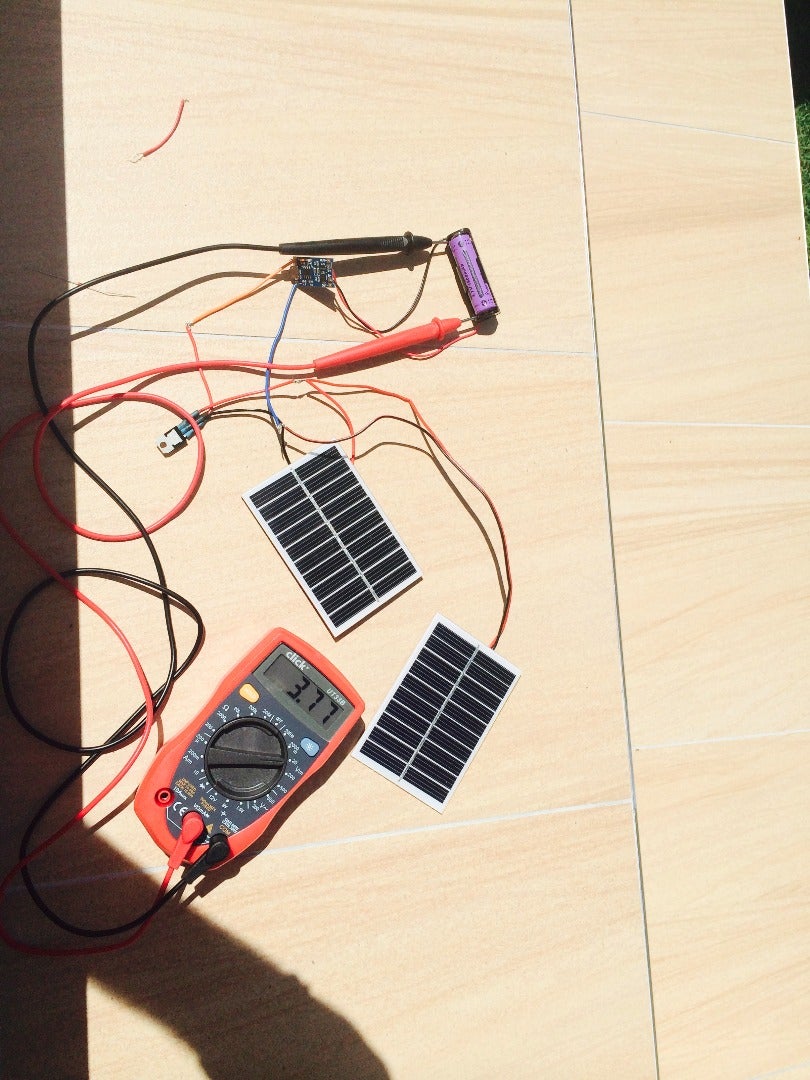
Reduce power consumption and consider ways to make the device more efficient; Deploy system with appropriately sized solar panel and battery; Publish data on the tago.io dashboard; An IoT ESP 32 Temperature Sensor. This tutorial will cover powering an ESP32 with a 6V solar panel and a 3.7V LiPo battery.

Can I Power my IoT Device with Solar Panels? Circuit Diagram
SunAirPlus - Solar Power Controller/Charger Data Collector; LiPo Battery; 6V 3.4W Solar Panel; Raspberry Pi as Data Logger / Analytics / Display; The system works as follows: SunAirPlus is hooked up to a solar panel and a LiPo battery. SunAirPlus handles all the complexities of properly charging and discharging a LiPo battery.

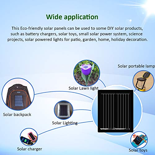
Wondering how to pick the right solar panel for your IoT device? We tested two IoT solar panels from Sparkfun to see if they can be used to run LoRaWAN appli Adding cheap and simple solar power to our small outdoor projects (e.g. ESP32, ESP8266, Arduino Pro Mini) removes the need to save energy or recharge batter
Solar energy for your IoT device Circuit Diagram
While IoT growth is staggering it will undoubtedly run into some future issues. One of the major barriers to the mass deployment of wireless IoT sensors is battery lifetime. Depending on power requirements, a primary battery will last a few months to a few years. Short battery life adds significant cost to a system over its lifetime.